Wrong SCL / SDA (MICROPY_HW_I2C0_SCL) for PIMORONI_TINY2040
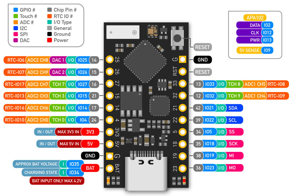
I am trying to get I2C working on my Tiny2040 board. Using the board as a responder in a responder/controller manner. I have some minimal code to set up the board using pin four as SDA and pin five as SCL as described in the GPIO diagrams below:
https://shop.pimoroni.com/products/tiny-2040
I am using https://github.com/epmoyer/I2CResponder/blob/main/i2c_responder.py with a minimal setup code that looks like the following on bus 0:
i2c_responder = I2CResponder(0, sda_gpio=0,scl_gpio=1,responder_address=0x41)
while 1:
    if i2c_responder.read_is_pending():
        i2c_responder.put_read_data(0x2)
And for testing, I tried on bus 1 as well against pin 6 and 7:
i2c_responder = I2CResponder(1, sda_gpio=6,scl_gpio=7,responder_address=0x41)
while 1:
    if i2c_responder.read_is_pending():
        i2c_responder.put_read_data(0x2)
I am using an RPI as a controller executing: sudo i2cdetect -y 1
Now the strange thing is:
- I get 0 response on bus 0 (i2cdetect detects no device)
- I get a signal on bus one and appear on my RPI (i2cdetect detects the device and I can query the value)
I was perusing the code and saw this:
https://github.com/micropython/micropython/blob/master/ports/rp2/boards/PIMORONI_TINY2040/mpconfigboard.h
#define MICROPY_HW_I2C0_SCL  (4)
#define MICROPY_HW_I2C0_SDA  (5)
Should it not be:
#define MICROPY_HW_I2C0_SCL  **(5)**
#define MICROPY_HW_I2C0_SDA  **(4)**
I tried to recompile the above with the mentioned change without much effect. Any thoughts?
esp32: Allow boards to configure I2C pins using new macros.
Adds ability to specify default I2C pins in ESP32 board definitions. eg.
/ports/esp32/boards/UM_TINYPICO/mpconfigboard.h
#define MICROPY_HW_I2C0_SCL (22)
#define MICROPY_HW_I2C0_SDA (21)
The TinyPICO board prefers I2C0 on pins SDA=21, SCL=22, rather than the default SDA=18, SCL=19
This change adds MICROPY_HW_I2C0_SCL and MICROPY_HW_I2C0_SDA to the UM_TINYPICO board def, used by machine_i2c.c, along with UM_FEATHERS2 and UM_TINYS2 boards.
Before:
>>> from machine import Pin, I2C
>>> i2c = I2C(0)
>>> i2c
I2C(0, scl=18, sda=19, freq=400000)
>>> i2c1 = I2C(1)
>>> i2c1
I2C(1, scl=25, sda=26, freq=400000)
After:
>>> from machine import Pin, I2C
>>> i2c = I2C(0)
>>> i2c
I2C(0, scl=22, sda=21, freq=400000)     <-- was 18 / 19
>>> i2c1 = I2C(1)
>>> print(i2c1)
I2C(1, scl=25, sda=26, freq=400000)
It works!
To make it consistent with STM32 and SPI board specific pin number overrides, I've rename the I2C defines
| from | to |
|---|---|
| I2C_0_DEFAULT_SCL | MICROPY_HW_I2C0_SCL |
| I2C_0_DEFAULT_SDA | MICROPY_HW_I2C0_SDA |
| I2C_1_DEFAULT_SCL | MICROPY_HW_I2C1_SCL |
| I2C_1_DEFAULT_SDA | MICROPY_HW_I2C1_SDA |